Adding multiple similar constraints in FPGA design can be tedious. A very common one is false path definition for each synchronization chain. Fortunately, in Vivado the XDC constraints are essentially Tcl commands. Therefore, we can easily create the false path constraints automation.
False path constraints for synchronization chain
One of the common aspects of FPGA designs is multiple clock domains. When a project uses multiple clock domains, signals often needs to cross from one domain to another. This is called Clock Domain Crossing (CDC). One of the most common ways to do so is to add several (at least 2) consecutive registers clocked by the target clock signal. The first register needs to be directly connected to the register in the source clock domain (with no logic between them). This design is often called a Synchronization Chain or a Synchronizer. Below you can see a schematic diagram of the described Synchronization Chain.
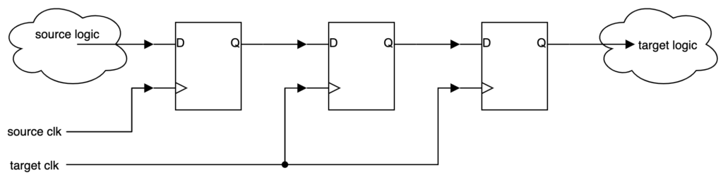
As you’ve probably noticed, the signal between the last register in the source clock domain and the first register in the target clock domain “special” in some sense. In fact it is. It sits in between the two clock domains and in both of them at the same time. Because of this, by default the tools will try to make this path meet the required timing constraints (setup & hold times). In most cases this would not be possible and would result in a design failing timing. For this reason every time we create a Synchronization Chain we add an additional constraint to instruct the STA (Static Timing Analysis) to ignore this path. This instruction is called a false-path. By default each Synchronizer requires a separate false-path constraint. This is another thing that we need to take care about. But we can also create a single constraint that will automatically take care of all Synchronization Chains. Let me show you how to do it.
False path constraints automation
Personally I prefer to create a separate module for a Synchronizer. And this approach has (among others) a great benefit that we can easily automate the false-path constraint creation.
For example, let’s say we added a Synchronizer.vhd file to our project. The module contains the following code:
library ieee;
use ieee.std_logic_1164.all;

entity Synchronizer is
generic (
   G_CDC_STAGES      : positive  := 2
);
port (
   i_clk             : in  std_logic;

   i_in              : in  std_logic;
   o_out             : out std_logic
);
end Synchronizer;

architecture RTL of Synchronizer is

signal sync_r        : std_logic_vector(G_CDC_STAGES-1 downto 0);

attribute ASYNC_REG  : string;
attribute ASYNC_REG  of sync_r  : signal is "TRUE";

begin

o_out                <= sync_r(sync_r'high);

process (i_clk)
begin
   if rising_edge(i_clk) then
      sync_r         <= sync_r(sync_r'high-1 downto 0) & i_in;
   end if;
end process;

end RTL;
Additionally we need to add a design constraint to define false paths. In case of Vivado the constraints are located in XDC file. To avoid adding new constraints for every single Synchronizer module instance, we can simply add the following line:
set_false_path -to [get_pins -filter {REF_PIN_NAME=~*D} -of_objects [get_cells -hierarchical -filter { FILE_NAME =~ */Synchronizer.vhd && NAME =~ */sync_r_reg[0]}]]How it works?
The XDC constraint above essentially gets all modules defined in Synchronizer.vhd file. From this modules it takes the first register’s D (data input) pin and applies the set_false_path constraint to the net connected to this input. Notice the difference between register name in the VHDL file and in the XDC constraint. During synthesis Vivado adds _reg suffix to each register created in a design.